Pipe Block
Pipes are built using logical entities called Pipe Blocks.
A Pipe Block is an object whose purpose is to modify a flow of values with strict time constraints. Pipe Blocks normally have both input and output flows of values.
Based on their functions, there are four kinds of Pipe Blocks:
| Function |
Description |
|---|---|
|
Input |
Works as generator of values:
|
|
Transformer |
|
|
Output (convertor) |
Block that can end a pipe:
|
|
Destination |
Simply models a physical axis of the machine |
The following table provides a short description of each Pipe Block:
Table 5-3: Pipe Network - List of Pipe Blocks
-
-
Below is some high-level information explaining the use of Pipe Blocks.
For an in-depth explanation, refer to Pipe Blocks Description.
Master

Use a Master Pipe Block to create a virtual master to link two or more axes. The Profile generator in the Master block is trapezoidal. If a parabolic type profile is required, use a PMP Pipe Block. If the master is an external encoder or another axis, use the Sampler Pipe Block.
Sampler

Use a Sampler Pipe Block to read an external encoder as an input signal into the Pipe Network or to directly read the actual position of another axis.
Gear
Use a Gearing Pipe Block to perform electronic gearing. The Gear Pipe Block allows gear ratios and the slope of the gear change to be initially set, then changed from within the application program.
Cam
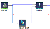
Use a Cam Pipe Block to optimize the motion profile. Use an Adder block with a Cam block to dynamically change the distance moved during each period (or modulo) of motion.

Cam Profiles are created using the cam creation tool.
Comparator
By tracking the position at one point of the Pipe Network, you can use a Comparator Pipe Block to synchronize when code is executed in a PLC application program.
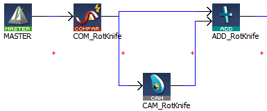
The following example shows the changing of the offset move by changing the amplitude (or offset) of the Cam Pipe Block.

In a PLC application program, the MLCompWriteRef function block is used to arm the comparator block and MLCompCheck function block is used to check the position. By using condition statements in a user program, specific actions (such as changing the move distance of the offset) can then be taken.
Another example shows the use of a Comparator Pipe Block to determine if a high-speed input is within the acceptable position range.
Trigger

Use a Trigger Pipe Block to read the position when a high-speed input is triggered on the machine. The trigger block allows you to “catch" the position at a particular location in the Pipe Network, as required by the application.
Delay
Use a Delay Pipe Block to delay the flow of position through a Pipe Network. One potential use is to place it before a Trigger block in a pipe which is not connected to a drive. There is a delay of five servo update cycles between the dynamic position in the Pipe Network and the triggering of a high-speed digital input.
Phaser
Use a Phaser Pipe Block to perform a dynamic phase adjustment inside the Pipe Network. This block can be used to phase-advance or phase-retard a position as required to synchronize different motion elements on a machine.
Synchronizer
Use a Synchronizer Pipe Block to synchronize two axes. This Pipe Block is useful in applications where it is necessary to start the motion of a second axis and sync to the first.
Axis
Models the link from the Pipe Network to a physical axis.
Changing Information Flow from Position to Velocity
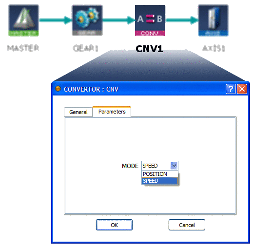
You can change the Pipe Network flow of information from position to velocity by using the Convertor Pipe Block. This Pipe Block is normally set up to receive position, so it must be changed to receive the expected input signal type as shown below:

Change the mode of Converter block to SPEED (and not POSITION mode).


